- VPN Overview: Encrypted Overlays on Untrusted Networks
- 1. How to Classify VPN Architectures
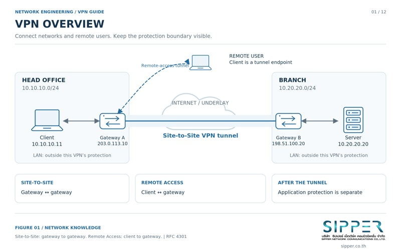
- 2. Tunnel Architecture and Security Boundaries
- 3. Packet Flow Through a Site-to-Site IPsec Tunnel
- 4. IPsec Architecture: IKE, ESP and Security Associations
- 5. IKEv2 and the Security Association Lifecycle
- 6. Comparing VPN Technologies
- 7. Routing Design and DNS Resolution
- 8. NAT, NAT-T and Firewall Interaction
- 9. Topologies and Four Design Scenarios
- 10. Performance, High Availability and MTU/MSS Tuning
- 11. Layered Security and Zero Trust
- 12. VPN for SIP Trunking and VoIP
- 13. VPN Compared with Related Technologies
- 14. A Layered Troubleshooting Method
- 15. Summary and Design Recommendations
- Standards and References
- FAQ
What Is a VPN? IPsec, WireGuard & Architecture
A VPN (Virtual Private Network) builds an encrypted, authenticated tunnel on top of a network you do not control, so headquarters, branches, data centers, cloud VPCs and remote staff can exchange traffic safely. This guide covers how tunnels work, packet flow, IPsec/IKEv2, WireGuard and OpenVPN, routing and NAT design, VoIP over VPN and a structured troubleshooting method.
VPN Overview: Encrypted Overlays on Untrusted Networks
Enterprises need predictable, protected paths between headquarters, branch offices, data centers, public cloud VPCs and a distributed workforce. Sending internal traffic across public IP infrastructure in clear text exposes it to eavesdropping, tampering and impersonation, because the organisation controls neither the routers in between nor who else can see the packets.
A Virtual Private Network (VPN) solves this by building a logical overlay on top of the physical network (the underlay). The original packet is encapsulated inside a new packet and protected with cryptography. Properly configured, a VPN provides three security properties between its two endpoints: confidentiality (the payload is encrypted), integrity with anti-replay (tampered or replayed packets are rejected) and peer authentication (each side proves its identity before keys are used).
Those guarantees stop at the tunnel endpoints. A VPN does not make a compromised laptop safe, does not make users anonymous, and does not decide which internal systems a connected user should reach. The rest of this guide explains where the protection begins and ends, and how to design, secure and troubleshoot IPsec/IKEv2, WireGuard and OpenVPN deployments, including real-time voice (SIP and RTP) carried over VPN links.
1. How to Classify VPN Architectures
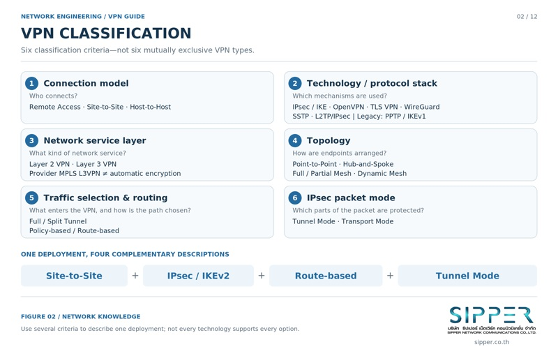
Vendor product names mix several independent design choices into one label. It is more useful to describe a VPN along separate technical dimensions, each of which answers a different question about the design.
A real deployment is a combination of these answers. For example, "Site-to-Site, IPsec/IKEv2, Route-based, Tunnel Mode" describes an inter-office link that negotiates keys with IKEv2, protects packets with ESP, selects traffic through a routed virtual tunnel interface and wraps each inner packet in a new outer IP header. Two terms are often confused: Full Tunnel is a forwarding policy (all client traffic goes through the VPN), while Full Mesh is a topology (every site has a direct tunnel to every other site). Likewise, IPsec Tunnel Mode describes packet encapsulation, not an internet routing policy.
| Dimension | Question it answers | Typical options |
|---|---|---|
| Endpoint topology | Where does the tunnel terminate? | Site-to-Site (gateway to gateway), Remote Access (client to gateway), host to host |
| Layer of operation | Does the tunnel carry Ethernet frames or IP packets? | Layer 2: L2TP, VXLAN/EVPN, OpenVPN tap. Layer 3: IPsec ESP, WireGuard, OpenVPN tun, GRE |
| Forwarding scope | Which client traffic enters the tunnel? | Full Tunnel (default route via VPN) or Split Tunnel (only corporate prefixes via VPN) |
| Traffic selection | How does the gateway decide what to encrypt? | Policy-based (traffic selectors, crypto maps) or Route-based (virtual tunnel interface, routing table) |
| Protocol suite | Which protocol negotiates keys and protects data? | IPsec (IKEv2 and ESP), WireGuard (Noise framework), OpenVPN (TLS control channel), SSTP (TLS) |
| Ownership | Who builds and operates the private network? | Customer-managed encrypted overlay over the internet, or provider-provisioned MPLS L3VPN (RFC 4364) |
2. Tunnel Architecture and Security Boundaries
Before choosing a protocol, it helps to be precise about what a tunnel is, what it does, and exactly which part of the path it protects.
Underlay, overlay and where tunnels terminate
The underlay is the physical forwarding network: ISP routers, transit providers and internet exchanges that move packets between public addresses. The overlay is the logical point-to-point link the VPN creates between two tunnel endpoints. Underlay routers only see the outer packet; they never need routes to the private networks inside.
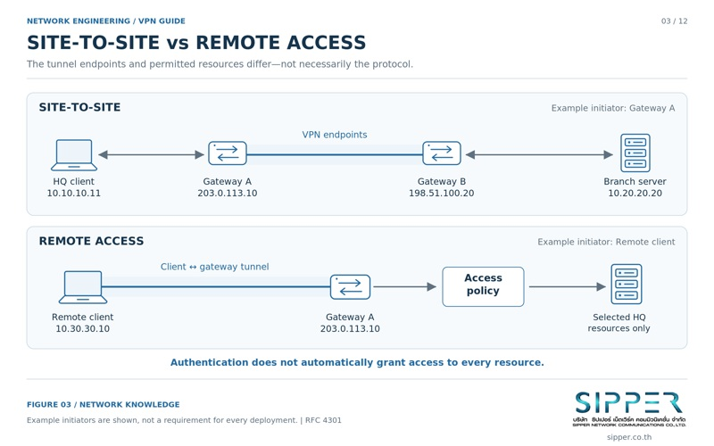
Endpoint placement defines the design. In a Site-to-Site VPN, tunnels terminate on firewalls or routers at each location, and ordinary LAN hosts send unencrypted traffic to their default gateway without any VPN software. In a Remote Access VPN, the tunnel terminates inside the user device on a virtual network adapter, so the gateway must decide explicitly what that user is allowed to reach once connected.
Four functions of an enterprise VPN
A production VPN combines four separate functions. Missing any one of them produces either a broken tunnel or an insecure one.
- Encapsulation: the original packet, including its IP header, is carried inside a new packet with a routable outer header, which lets private RFC 1918 addresses cross the internet.
- Encryption: symmetric ciphers such as AES-GCM or ChaCha20-Poly1305 turn the inner packet into ciphertext that intermediate devices cannot read.
- Integrity and anti-replay: an authentication tag or HMAC detects modification, and a sequence-number window rejects replayed packets (RFC 4303 for ESP).
- Access control: authenticating the peer does not authorise everything. The terminating gateway must still apply firewall rules and least-privilege policy to the decrypted traffic.
Security boundary: gateway-to-gateway is not end-to-end
In a Site-to-Site design, encryption exists only between Gateway A and Gateway B. The LAN segments from the client to Gateway A and from Gateway B to the server are carried in clear text on the local network.
If the threat model includes insiders, lateral movement or shared local switching, protect the application itself as well: HTTPS/TLS for web and API traffic, SIP over TLS and SRTP for voice. A VPN adds a protected transport between sites; it does not replace application-layer encryption on the LAN.
3. Packet Flow Through a Site-to-Site IPsec Tunnel
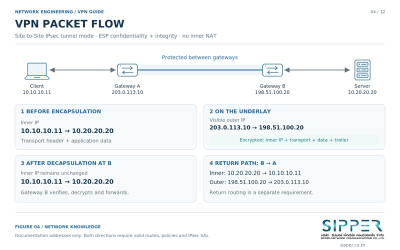
The easiest way to understand IPsec is to follow one packet. The example below uses a route-based Site-to-Site tunnel in IPsec Tunnel Mode with ESP providing confidentiality and integrity. Public addresses come from the documentation ranges in RFC 5737, and the internal ranges are private RFC 1918 space.
| Entity | Address | Role |
|---|---|---|
| Client A (headquarters) | 10.10.10.11 | Host that starts the session |
| Gateway A, LAN side | 10.10.10.1 | Default gateway for Client A |
| Gateway A, WAN side | 203.0.113.10 | Public IPsec endpoint of headquarters |
| Gateway B, WAN side | 198.51.100.20 | Public IPsec endpoint of the branch |
| Gateway B, LAN side | 10.20.20.1 | Default gateway for Server B |
| Server B (branch) | 10.20.20.20 | Destination application server |
Outbound: from Client A to Server B
Client A builds a packet from 10.10.10.11 to 10.20.20.20, for example a TCP SYN to port 443. The destination is off-link, so the packet goes to Gateway A. Gateway A then processes it according to the IPsec architecture in RFC 4301, and Gateway B reverses the process.
- Route lookup: Gateway A resolves 10.20.20.0/24 to the virtual tunnel interface.
- Policy lookup: the Security Policy Database (SPD) marks this traffic as PROTECT.
- SA lookup: the Security Association Database (SAD) provides the outbound Child SA keys, algorithms and Security Parameter Index (SPI).
- Encapsulation: the whole inner packet is encrypted, an ESP header and trailer plus an integrity check value (ICV) are added, and a new outer header from 203.0.113.10 to 198.51.100.20 is prepended.
- Transit: internet routers see only the outer header, carried as native ESP (IP protocol 50) or as ESP-in-UDP on port 4500 when NAT Traversal is active.
- Decapsulation: Gateway B finds the inbound SA by SPI, verifies the ICV and the anti-replay window, decrypts, checks its firewall policy, and forwards the original packet to 10.20.20.20.
Return path and routing symmetry
Server B replies from 10.20.20.20 to 10.10.10.11. That reply must reach Gateway B, either because Gateway B is the default gateway of Server B or because Server B has a specific route for 10.10.10.0/24 pointing to it.
If Server B uses a different internet router without that route, the reply leaves unencrypted toward a network where the private destination is not routable, and it never returns to Client A. The tunnel status still shows up while the application times out. A working VPN requires routing that is correct in both directions at both sites.
4. IPsec Architecture: IKE, ESP and Security Associations
IPsec separates the work of agreeing keys from the work of protecting each packet. Keeping these two planes apart explains most IPsec behaviour, and most IPsec failures.
Control plane (IKE) and data plane (ESP)
The control plane is IKE, today IKEv2. It authenticates the peers, runs a Diffie-Hellman exchange, negotiates algorithms and traffic selectors, and creates, rekeys and deletes security associations. IKE uses UDP port 500, and UDP port 4500 once NAT is detected.
The data plane is ESP (Encapsulating Security Payload, IP protocol 50, RFC 4303), which provides confidentiality, data origin authentication, integrity and anti-replay for each packet. AH (Authentication Header, IP protocol 51) provides integrity without encryption, but it also protects fields of the outer IP header, so it breaks when NAT rewrites addresses. AH is rarely used in modern designs.
IKE SA, Child SA, SPD and SAD
Four data structures drive IPsec processing. Knowing which one is involved narrows troubleshooting quickly.
- IKE SA: the authenticated, encrypted control channel between the peers. It carries rekeying, liveness checks and Child SA negotiation.
- Child SA (IPsec SA): the keys and algorithms used for data. Child SAs are unidirectional and created in pairs, one inbound and one outbound, each with its own SPI.
- Security Policy Database (SPD): rules keyed on selectors such as addresses, protocol and ports, with the actions PROTECT, BYPASS or DISCARD.
- Security Association Database (SAD): the active SAs, indexed for inbound packets by SPI, holding keys, algorithms and replay counters.
Tunnel mode versus transport mode
Tunnel mode encrypts the entire original IP packet and adds a new outer IP header. It is the normal choice for Site-to-Site VPNs because internal addresses are hidden inside the encrypted payload and private address space can cross the internet.
Transport mode inserts the ESP header after the original IP header and protects only the payload, leaving the original addresses visible. It suits host-to-host protection and is commonly used underneath GRE over IPsec or L2TP/IPsec, where another protocol already supplies the tunnel header.

5. IKEv2 and the Security Association Lifecycle
IKEv2 is defined in RFC 7296. It replaced IKEv1, which RFC 9395 formally deprecates and whose specifications are now Historic. IKEv2 needs fewer messages, has NAT detection and liveness checks built in, and supports EAP for user authentication in Remote Access designs.
IKE_SA_INIT, IKE_AUTH and CREATE_CHILD_SA
In the normal case a tunnel is ready after two request and response exchanges, four messages in total. Extra round trips occur with cookie challenges, a rejected Diffie-Hellman group, EAP authentication or additional intermediate exchanges, so four messages is a minimum rather than a fixed rule.
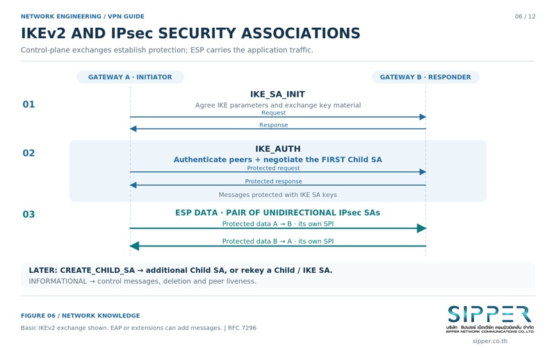
- IKE_SA_INIT: the peers agree on algorithms (encryption, integrity, PRF, Diffie-Hellman group), exchange nonces and key-exchange values, detect NAT, and derive the keys that protect the IKE SA.
- IKE_AUTH: inside that protected channel, each side sends its identity (IDi and IDr), proves it with a certificate signature or pre-shared key, and negotiates traffic selectors for the first Child SA pair.
- CREATE_CHILD_SA: used later to add Child SAs or to rekey existing SAs without repeating authentication.
Pre-shared keys versus X.509 certificates
A pre-shared key (PSK) is the same secret configured on both peers. It is simple for a handful of tunnels, but reusing one key across branches makes individual revocation impossible. Weak keys are easier to guess or expose, so use a sufficiently long random secret and a distinct key for each peer pair.
Certificates give each gateway its own private key and a certificate issued by a trusted certificate authority. This scales better, avoids distributing shared secrets and allows one site to be revoked through a CRL or OCSP without touching the others. The cost is operating a PKI: issuance, renewal and revocation checking.
Algorithms: encryption, integrity, PRF and Diffie-Hellman
RFC 8247 (IKEv2) and RFC 8221 (ESP) list which algorithms implementations must, should and should not support. They are updated over time, so check the current versions and your compliance requirements rather than copying an old proposal list.
- Encryption: AEAD ciphers such as AES-GCM combine encryption and integrity in one transform and are the usual modern choice.
- Integrity: only needed as a separate transform with non-AEAD ciphers such as AES-CBC, for example HMAC-SHA2-256-128.
- PRF: derives key material from the Diffie-Hellman result and nonces, for example PRF_HMAC_SHA2_256.
- Diffie-Hellman groups: 2048-bit MODP (group 14) and elliptic-curve groups such as 19, 20 or Curve25519 (group 31) are common choices; small legacy groups such as 1, 2 and 5 should be disabled.
Rekeying, reauthentication and Perfect Forward Secrecy
Rekeying creates fresh keys and a new SA before the old one expires, so traffic continues without interruption. Reauthentication goes further and repeats peer authentication by building a new IKE SA, which re-validates credentials such as certificates.
Perfect Forward Secrecy (PFS) performs a new Diffie-Hellman exchange when Child SAs are created or rekeyed. This limits the damage of a later key compromise: traffic protected with keys derived from an earlier, independent exchange is not exposed simply because a later key or long-term credential leaks. It is a strong mitigation, not a guarantee against every attack.
What must match between peers and what is local policy
Some parameters must be compatible on both sides or negotiation fails: at least one common proposal, acceptable identities, valid credentials and trust chains, and traffic selectors that the responder accepts. Other settings are local policy: SA lifetimes can differ because the side with the shorter lifetime simply rekeys first, and liveness-check intervals and queuing are chosen per gateway.
6. Comparing VPN Technologies
No single VPN protocol is best in every situation. The choice balances throughput, operating system support, firewall and NAT traversal, identity management and compliance requirements. The table summarises typical characteristics; exact behaviour depends on the implementation and version.
| Technology | Typical use | Transport and traversal | Identity and keys | Main trade-offs |
|---|---|---|---|---|
| IPsec / IKEv2 | Site-to-Site links and managed Remote Access | UDP 500, UDP 4500 with NAT-T, or native ESP; sometimes blocked on restrictive guest networks | Pre-shared keys, X.509 certificates, EAP for users | Broad vendor and OS support and hardware acceleration; configuration has many interdependent parameters |
| WireGuard | Site-to-Site, cloud links and modern remote access | One configurable UDP port; works through NAT but not where UDP is blocked | Static Curve25519 public keys per peer; no built-in PKI or user directory | Small codebase and fixed modern cryptography; user identity, MFA and key distribution need extra tooling |
| OpenVPN | Cross-platform Remote Access and some Site-to-Site | UDP preferred; TCP 443 when UDP is blocked | TLS with X.509 certificates, optional user authentication | Very flexible; user-space data path costs performance unless data channel offload is used |
| SSTP | Remote Access in Windows-centric environments | TLS over TCP 443 | Server TLS certificate plus user authentication | Microsoft protocol; TCP transport suffers on lossy links |
| TLS web portal (clientless) | Browser access to selected internal web apps | HTTPS over TCP 443 | Web server certificate plus user login | Only reaches published web applications, not a full network-layer tunnel |
OpenVPN: TLS control channel and data channel
OpenVPN uses a TLS session as its control channel for authentication and key exchange, and a separate data channel that encrypts tunnelled packets with keys derived from that session.
UDP transport is preferred. When OpenVPN runs over TCP and the underlay loses packets, both the inner TCP connections and the outer TCP connection retransmit and back off at the same time, a problem often called TCP meltdown, and throughput can collapse. Reserve TCP mode for networks that block UDP.
WireGuard: cryptokey routing
WireGuard, described in its whitepaper by Jason Donenfeld, uses a fixed set of modern primitives (Noise protocol framework, Curve25519, ChaCha20-Poly1305, BLAKE2s) with no algorithm negotiation. Each peer is identified by a public key and a list of AllowedIPs. When sending, the destination address selects the peer; when receiving, the decrypted source address must fall inside that peer’s AllowedIPs or the packet is dropped.
Because WireGuard has no built-in user directory, certificate authority or configuration push, enterprise deployments usually add a control plane for key distribution, single sign-on and device posture. A fixed algorithm set also means organisations with mandated algorithm lists should confirm that WireGuard satisfies them.
TLS VPNs and legacy protocols
"SSL VPN" is a product label, not a protocol. What matters is the TLS configuration underneath: allow only TLS 1.2 and TLS 1.3, following RFC 8996, which deprecates TLS 1.0 and 1.1, and the recommendations in RFC 9325.
Retire legacy protocols. PPTP relies on MS-CHAPv2 authentication, which is considered broken, and should not be deployed. L2TP on its own provides no encryption and should only be used as L2TP/IPsec, if at all.
7. Routing Design and DNS Resolution
Most VPN problems reported as "the tunnel does not work" are really routing or name resolution problems. Two routing decisions matter most: which client traffic enters the tunnel, and how the gateway selects traffic to encrypt.
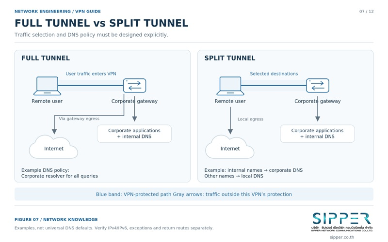
Full Tunnel versus Split Tunnel
Full Tunnel replaces the client default route (0.0.0.0/0, and ::/0 for IPv6) so that all traffic, including internet browsing, goes through the corporate gateway. The benefit is central inspection, filtering, data loss prevention and logging. The cost is corporate bandwidth and extra latency to cloud services, because traffic detours through the gateway before reaching the internet.
Split Tunnel installs routes only for corporate prefixes, for example 10.0.0.0/8 or 172.16.0.0/12, and sends everything else directly through the local ISP. It saves bandwidth and gives users direct access to cloud services, but the device is connected to the corporate network and the internet at the same time with less central visibility. The NSA and CISA remote access VPN guidance treats split tunnelling as a risk to be justified and compensated with endpoint controls.
Policy-based VPN versus Route-based VPN
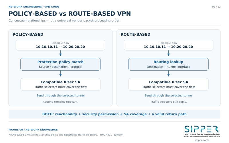
A Policy-based VPN (the classic crypto map model) matches traffic against selectors such as source subnet and destination subnet and encrypts whatever matches as it leaves the physical interface. It is simple for one or two fixed subnet pairs, but adding subnets means changing selectors on both peers, per-tunnel counters are limited, and dynamic routing protocols generally cannot run over it.
A Route-based VPN binds IPsec to a virtual tunnel interface (VTI) or GRE interface. Whatever the routing table sends to that interface is encrypted. This supports BGP or OSPF over the tunnel, redundant tunnels with automatic failover, multicast where the platform allows it, and zone-based firewall policy on the tunnel interface. Most multi-site and cloud designs use the route-based model.
Internal DNS, DNS leaks and dual-stack clients
Name resolution needs the same attention as routing, because a correct tunnel is useless if clients cannot find internal services or silently send queries elsewhere.
- Internal names: remote clients must receive corporate DNS servers or conditional forwarding so names such as app.corp.example resolve to internal addresses.
- DNS leaks: in a Full Tunnel design, clients that keep querying the home router or ISP resolver reveal which sites they visit. Operating system policy, for example the Windows Name Resolution Policy Table (NRPT), can force the right queries through the VPN.
- IPv6: if the tunnel carries only IPv4 while the local network offers IPv6, IPv6 traffic can bypass the tunnel entirely. Either carry IPv6 through the VPN or block it on the client while connected.
8. NAT, NAT-T and Firewall Interaction
Address translation and firewalls sit on almost every VPN path. They affect IPsec in three ways: NAT between the peers, NAT applied to tunnel traffic by mistake, and filtering at the gateway itself.
NAT Traversal (NAT-T) for ESP
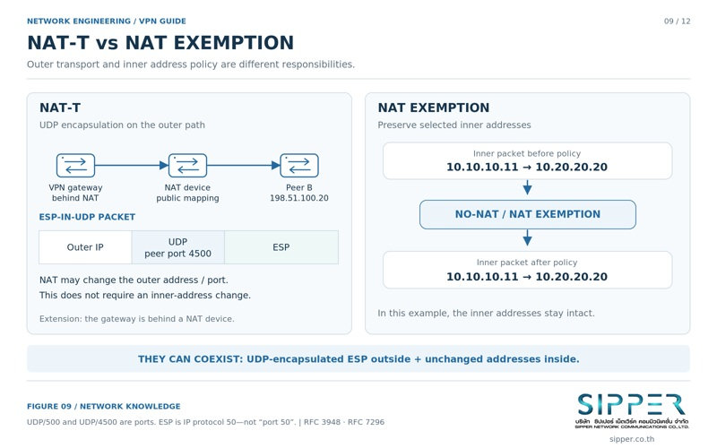
Port address translation (PAT, also called NAPT) lets many private hosts share one public address by tracking TCP and UDP port numbers. Native ESP is its own IP protocol and has no ports, so a PAT device cannot build a reliable mapping for it and return traffic is lost.
IKEv2 detects NAT during IKE_SA_INIT using NAT detection payloads defined in RFC 7296. If NAT is present, IKE moves from UDP 500 to UDP port 4500 and ESP packets are wrapped in UDP port 4500 as defined in RFC 3948 (ESP-in-UDP). To the NAT device this looks like an ordinary UDP flow. Periodic NAT keepalives stop the mapping from expiring when the tunnel is idle.
NAT exemption for tunnel traffic
Between sites, hosts should normally keep their real private addresses, for example 10.10.10.0/24 at headquarters and 10.20.20.0/24 at the branch, so routing, logging and access policy stay consistent.
Perimeter firewalls usually apply source NAT to everything heading to the internet. Unless a NAT exemption (no-NAT) rule for site-to-site traffic is evaluated before that general rule, packets are translated to the public address, no longer match the tunnel selectors or policy, and never reach the tunnel correctly.
Public addresses, double NAT and CGNAT
At least one peer must be reachable: a static public address, or a dynamic DNS name that tracks it, acting as responder. The other peer can sit behind NAT and act as initiator, keeping the mapping open with NAT keepalives.
If both sites sit behind carrier-grade NAT (CGNAT, typically 100.64.0.0/10 from RFC 6598), neither can accept inbound connections. The options are a public address from the ISP, a relay or hub in the cloud that both sites connect out to, or an overlay product that provides relaying.
Two layers of firewall policy
Protect the outside interface by allowing only what the VPN needs: UDP 500, UDP 4500 and, if NAT-T is not always used, IP protocol 50, restricted to known peer addresses where possible. Then treat traffic that comes out of the tunnel as untrusted too: inspect it with an internal policy on the tunnel interface or zone and allow only the destinations and ports each site or user group needs.
9. Topologies and Four Design Scenarios
Topology decides how traffic moves between sites and how much configuration grows with each new site. The scenarios that follow show how the building blocks above combine in common designs.
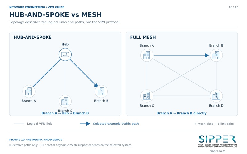
Point-to-point, Hub-and-Spoke and Full Mesh
Each topology trades path efficiency against the number of tunnels to build and maintain.
- Point-to-point: one tunnel between two sites, for example a data center replication link.
- Hub-and-Spoke: every branch connects only to a central hub. Policy is managed in one place, but branch-to-branch traffic must pass through the hub (hairpinning), which adds an extra leg of latency and makes the hub a critical dependency that needs redundancy.
- Full Mesh: every site has a direct tunnel to every other site, which gives the shortest paths. The number of tunnels grows as N(N-1)/2, quadratically with the number of sites, so large networks use dynamic approaches such as DMVPN or SD-WAN that build direct tunnels on demand.
Scenario 1: Site-to-Site branch interconnect
Requirement: connect headquarters (10.10.0.0/16) with two branches (10.20.0.0/16 and 10.30.0.0/16) for ERP and database traffic. Design: route-based IPsec tunnels with IKEv2, AEAD encryption such as AES-256-GCM and an elliptic-curve Diffie-Hellman group, certificate authentication, and BGP over the tunnel interfaces so prefixes are advertised automatically and traffic reroutes when a link fails.
Scenario 2: Remote Access for a mobile workforce
Requirement: staff on hotel or public Wi-Fi need the ERP system and internal file servers. Design: IKEv2 with EAP, or a managed WireGuard or OpenVPN service, integrated with the corporate identity provider; mandatory multi-factor authentication; a dedicated client address pool such as 172.16.100.0/24; device posture checks; and firewall rules that grant each group only the applications it needs.
Scenario 3: Hybrid cloud interconnect
Requirement: resilient connectivity between an on-premises data center and cloud VPCs or virtual networks. Design: two IPsec tunnels to the cloud provider’s VPN gateway endpoints, ideally from two on-premises devices or ISPs, with BGP on both tunnels. Use provider-supported BGP attributes such as AS-path prepending or MED to prefer one path, and follow the provider documentation for supported algorithms and limits.
Scenario 4: Overlapping subnets with twice NAT
Requirement: headquarters uses 10.10.10.0/24 and a newly connected partner uses the same range, so neither side can route to the other. The permanent fix is to renumber one side. When that is not possible yet, each site is presented across the tunnel as a unique virtual subnet: headquarters as 10.110.10.0/24 and the partner as 10.210.10.0/24, with the gateways translating source and destination (twice NAT).
- Client A (10.10.10.11) sends to the partner’s virtual address 10.210.10.20.
- Gateway A translates the source to 10.110.10.11 and sends the packet into the tunnel.
- Gateway C translates the destination to the real server 10.10.10.20 and delivers it.
- Server C replies to 10.110.10.11; Gateway C translates the source to 10.210.10.20 and sends the reply into the tunnel.
- Gateway A translates the destination back to 10.10.10.11 and delivers the reply to Client A.
10. Performance, High Availability and MTU/MSS Tuning
A tunnel adds headers, cryptographic work and dependence on the underlay. Planning for those costs prevents the most frustrating class of VPN faults: connections that establish but then stall.
MTU, Path MTU Discovery and TCP MSS clamping
Ethernet paths usually carry a 1,500-byte MTU. Encapsulation makes a full-size inner packet larger than that. If the packet has the Don’t Fragment (DF) bit set, a router on the path drops it and should send back an ICMP Fragmentation Needed message (IPv4 type 3, code 4). When a firewall blocks that ICMP message, Path MTU Discovery fails and a black hole appears: small packets, pings and the TCP handshake work, but large transfers and TLS handshakes with big certificates hang.
Adding the example overhead below to a full inner packet shows why. Overhead depends on the cipher, NAT-T, IP version and any additional encapsulation such as PPPoE or GRE, so treat these figures as one worked example rather than a universal constant.
- Outer IPv4 header: 20 bytes; UDP header for NAT-T: 8 bytes.
- ESP header (SPI and sequence number): 8 bytes; AES-GCM initialization vector: 8 bytes.
- ESP trailer (pad length and next header): 2 bytes plus 0 to 3 bytes of padding; AES-GCM ICV: 16 bytes.
- Total in this example: 62 to 65 bytes, so the largest inner packet on a 1,500-byte underlay is about 1,435 bytes and the arithmetic TCP MSS is about 1,395 bytes (inner packet minus 40 bytes of IPv4 and TCP headers).
- In practice many teams clamp the MSS lower, commonly around 1,350 to 1,380 bytes, to leave headroom for PPPoE (8 bytes), GRE, an IPv6 outer header, CBC ciphers or TCP options. Measure the real path MTU and confirm your vendor guidance.
Throughput and cryptographic offload
Firewall datasheet throughput is usually measured without encryption. IPsec throughput is lower and depends on packet size, cipher and whether the platform uses hardware acceleration such as AES-NI instructions or dedicated crypto engines. Size gateways on the vendor’s IPsec figures at realistic packet sizes, including small voice packets, not on plain firewall throughput.
Latency, loss and tunnel failover
A tunnel cannot be better than its underlay. Latency lowers TCP throughput for a given window size, and packet loss causes TCP retransmissions and audible gaps in real-time media.
Liveness detection lets a gateway notice a dead peer. IKEv2 includes liveness checks natively (RFC 7296); Dead Peer Detection in RFC 3706 is the equivalent extension for IKEv1. When a peer stops responding, the gateway removes the stale SAs, and with route-based tunnels a dynamic routing protocol or tracked static routes can move traffic to a backup tunnel or second ISP.
11. Layered Security and Zero Trust
A VPN is an encrypted transport, not a statement that everything behind it can be trusted. Treating a connected VPN session as permission to reach the whole network is the design error behind many breaches.
Security therefore comes from layers around the tunnel: strong identity, least-privilege access, protected credentials, a patched gateway, healthy endpoints and good logging.
What a VPN does not do
A VPN protects traffic between its endpoints. It does not protect a device that is already compromised: malware on a laptop sees data before it is encrypted and can use the tunnel like the legitimate user. It does not provide anonymity: the VPN operator, and the services you reach, can still observe and log activity. It does not replace application security, patching or backup.
Least privilege, Zero Trust and ZTNA
NIST SP 800-207 describes Zero Trust architecture: no implicit trust based on network location, and access decisions made per request using identity, device state and context. A VPN can be one component of such an architecture, but a VPN by itself is not Zero Trust.
In practice this means microsegmentation, per-group firewall rules that allow only specific applications and ports, and for many remote users a ZTNA (Zero Trust Network Access) service that brokers access to individual applications instead of placing the device on the internal network.
Credential lifecycle and revocation
Keys and certificates need governance just like passwords.
- Store gateway private keys in non-exportable storage or a hardware security module (HSM) where the platform supports it.
- Track certificate expiry and automate renewal so tunnels do not fail unexpectedly.
- Check revocation through CRL or OCSP so that departing staff and lost or compromised devices lose access promptly.
Gateway hardening, endpoint posture and logging
Internet-facing VPN gateways are frequent targets, and published vulnerabilities in them are exploited quickly. The NSA and CISA guidance on selecting and hardening remote access VPN solutions (September 2021) and NIST SP 800-77 Rev. 1 recommend the following controls.
- Choose supported products, apply security updates promptly and reduce the exposed management surface.
- Require multi-factor authentication for remote users and check device posture where possible: endpoint protection, disk encryption and operating system patch level.
- Send connection, authentication and traffic-volume events to a central SIEM and alert on anomalies such as impossible travel or repeated failures.
12. VPN for SIP Trunking and VoIP
Voice over a VPN behaves differently from ordinary data traffic. Signalling and media travel separately, media is sensitive to delay and loss, and several security layers overlap. The table shows how the common components divide the work.
| Component | Scope | Considerations |
|---|---|---|
| VPN (IPsec or WireGuard) | Protects all IP traffic between the tunnel endpoints | Secures WAN transit; does not inspect or understand SIP and does not protect LAN segments |
| Session Border Controller (SBC) | SIP and RTP security at the application layer | Topology hiding, SIP normalisation, toll-fraud and flood protection, media anchoring |
| SIP over TLS | Encrypts call signalling, commonly on TCP port 5061 | Protects credentials and call metadata; does not encrypt the audio |
| SRTP | Encrypts the RTP media payload (RFC 3711) | Protects the conversation, including on LAN segments outside the VPN |
Multi-site PBX interconnect
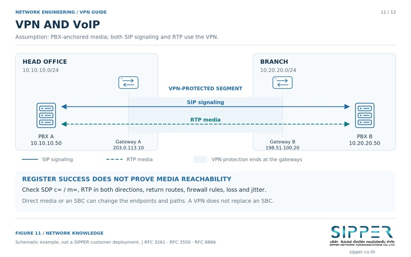
Linking PBXs at headquarters and branches over VPN allows extension dialling between sites and central trunking. For example, a headquarters PBX at 10.10.10.50 can form a SIP trunk with a branch PBX at 10.20.20.50 across the IPsec tunnel between the site gateways, so inter-site calls stay on the private network.
SIP signalling and RTP media are separate flows
SIP (RFC 3261) sets up and tears down calls, usually on UDP or TCP port 5060. RTP (RFC 3550) then carries the audio on dynamic UDP ports negotiated in SDP. The port range is set by each PBX or phone; many systems default to a range such as 10000 to 20000.
The classic fault is one-way audio or no audio: the call rings and connects but nobody hears anything. Common causes are firewall or tunnel policy that allows SIP but not the RTP port range, SDP bodies that advertise addresses the other side cannot reach, or a SIP ALG on the gateway rewriting packets incorrectly.
Voice quality: QoS, DSCP and the path
Voice sends small packets at fixed intervals, for example every 20 ms for G.711. ITU-T G.114 recommends keeping one-way delay under about 150 ms for good interactivity; jitter below roughly 30 ms and packet loss below about 1 percent are common engineering targets rather than formal limits.
Mark RTP with DSCP EF (Expedited Forwarding, value 46) and make sure the gateway copies the inner DSCP value to the outer tunnel header, then prioritise it in the egress queue. QoS only works on links you control or where a provider honours markings; the public internet generally ignores them. Priority queuing after encryption can also reorder packets, so confirm the anti-replay window is large enough on busy links.
13. VPN Compared with Related Technologies
Several technologies overlap with VPNs in enterprise networks. Knowing where each one stops avoids buying or designing for the wrong problem.
These technologies usually work together as layers: SD-WAN chooses the transport, IPsec encrypts internet links, and ZTNA brokers access to sensitive applications for remote users.
| Technology | Primary role | Security relationship |
|---|---|---|
| IPsec or TLS VPN | Encrypted overlay tunnels across untrusted IP networks | Provides confidentiality, integrity and peer authentication between tunnel endpoints |
| MPLS L3VPN (RFC 4364) | Carrier-provided routing separation using MP-BGP and VRFs | Separates customer traffic in the provider network but does not encrypt it; add IPsec when confidentiality is required |
| SD-WAN | Centrally managed steering of traffic across several WAN links | Most products build IPsec overlays automatically and add application-aware path selection |
| ZTNA | Per-application access broker based on user and device context | Replaces broad network-level access with per-application access and continuous evaluation |
| Forward or reverse proxy | Application-layer intermediary for HTTP and HTTPS | Works only for the protocols it proxies; not a general network-layer tunnel |
| SSH tunnelling | Port forwarding over an SSH session | Useful for ad hoc administrative access; not suited to interconnecting enterprise subnets |
14. A Layered Troubleshooting Method
When a VPN fails, work from the bottom up and change one variable at a time. For IPsec/IKEv2, check five layers in order, because each layer depends on the one below it.
Do not disable perimeter firewalls or weaken cryptography to "see if it helps" in production. That creates exposure and usually hides the real cause. The table maps eight common symptoms to likely causes and checks.
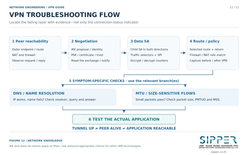
- Layer 1: peer reachability across the underlay, including UDP 500 and 4500.
- Layer 2: control plane, whether the IKE SA is established and authenticated.
- Layer 3: data plane, whether Child SAs exist in both directions with matching selectors.
- Layer 4: routing, NAT exemption and firewall policy for the decrypted traffic.
- Layer 5: application behaviour, DNS, MTU and voice quality.
| Symptom | Likely causes | What to check |
|---|---|---|
| Peer does not respond | UDP 500 or 4500 blocked; wrong peer address; WAN link down | Reachability of the peer public address, edge firewall rules for UDP 500 and 4500, WAN interface state |
| IKE negotiation or authentication fails | No common proposal; wrong PSK; expired or untrusted certificate; identity mismatch | IKE logs on both peers and notify messages such as NO_PROPOSAL_CHOSEN or AUTHENTICATION_FAILED |
| IKE SA up, Child SA fails | ESP proposal mismatch; traffic selectors not accepted | Child SA state in both directions, negotiated selectors, TS_UNACCEPTABLE notifications |
| Tunnel up, no traffic passes | Missing route; firewall blocks decrypted traffic; source NAT applied to tunnel traffic | Routing tables, NAT exemption order, encrypt and decrypt counters on both gateways |
| Requests leave, replies never arrive | Missing return route; asymmetric routing; host firewall on the server | Packet capture on the server and gateway, server default gateway and route back to the client pool |
| IP addresses work, names do not | Wrong DNS servers; queries leaking to the local resolver; missing search suffix | nslookup or dig on the client, split DNS or NRPT policy, active resolver on the VPN interface |
| Small packets work, large transfers hang | MTU black hole; ICMP Fragmentation Needed blocked | Ping with the DF bit and increasing sizes, allow the ICMP message, clamp TCP MSS |
| Drops during rekey | PFS group mismatch; reauthentication failures; expiring NAT mappings | Correlate drop times with SA lifetimes and CREATE_CHILD_SA log entries, check NAT keepalives |
15. Summary and Design Recommendations
A reliable VPN starts from requirements rather than products: who connects, from where, to which resources, with what compliance obligations. IPsec/IKEv2 remains the interoperable standard for Site-to-Site links and managed Remote Access; WireGuard offers a small, fast and simple data plane when identity and key management are handled around it; OpenVPN and TLS-based options help where only TCP 443 gets through.
For most organisations, prefer route-based tunnels with certificates and dynamic routing, decide deliberately between Full Tunnel and Split Tunnel, plan NAT exemption, NAT-T and MTU/MSS from the start, and treat decrypted traffic as untrusted until policy allows it.
For voice, remember that SIP and RTP are separate flows, allow the RTP range explicitly, mark media with DSCP EF where the path honours it, and use TLS and SRTP when calls must stay private on the LAN. Above all, pair the VPN with Zero Trust controls, since the tunnel protects the path, not the endpoint or access decisions.
Standards and References
The main primary sources behind this guide are listed below. Standards are revised over time, so check the current status of each document, and your vendor documentation, before relying on a specific requirement.
| Reference | Subject | Used for |
|---|---|---|
| RFC 4301 | Security Architecture for the Internet Protocol | SPD, SAD and IPsec processing model |
| RFC 4303 | IP Encapsulating Security Payload (ESP) | ESP confidentiality, integrity and anti-replay |
| RFC 7296 | Internet Key Exchange Protocol Version 2 (IKEv2) | IKEv2 exchanges, NAT detection and liveness checks |
| RFC 9395 | Deprecation of IKEv1 and obsoleted algorithms | Status of IKEv1 |
| RFC 8221 and RFC 8247 | Algorithm implementation requirements for ESP and IKEv2 | Cipher, PRF and Diffie-Hellman group guidance |
| RFC 3948 | UDP Encapsulation of IPsec ESP Packets | NAT-T and ESP-in-UDP on port 4500 |
| RFC 4364 | BGP/MPLS IP Virtual Private Networks | MPLS L3VPN architecture |
| RFC 8996 and RFC 9325 | Deprecating TLS 1.0 and 1.1; secure use of TLS | TLS requirements for TLS-based VPNs |
| NIST SP 800-77 Rev. 1 | Guide to IPsec VPNs (June 2020) | IPsec planning and deployment practice |
| NIST SP 800-207 | Zero Trust Architecture (August 2020) | Zero Trust principles and components |
| NSA and CISA guidance | Selecting and Hardening Remote Access VPN Solutions (September 2021) | Gateway hardening, patching and MFA |
| WireGuard whitepaper | WireGuard: Next Generation Kernel Network Tunnel (J. A. Donenfeld) | Cryptokey routing and protocol design |
Frequently Asked Questions
Ready to deploy?
SIPPER designs, deploys, and maintains end-to-end enterprise phone systems. Start with a free quote.